
Ever wondered if your robotic arm is doing more than you expect? It’s like when you check if every link in a strong chain can support a heavy load. Calculating load capacity can be broken down into simple, clear formulas that connect mass, distance, and gravity.
In essence, this guide takes you on a quick tour of how joint torque (that’s the force making a joint rotate) and moment calculations work in your system. Understanding these numbers is key to keeping your technology safe and efficient. And honestly, knowing this can really boost your performance while helping you dodge unexpected issues.
Essential Formulas for Robotic Arm Load Capacity Calculation
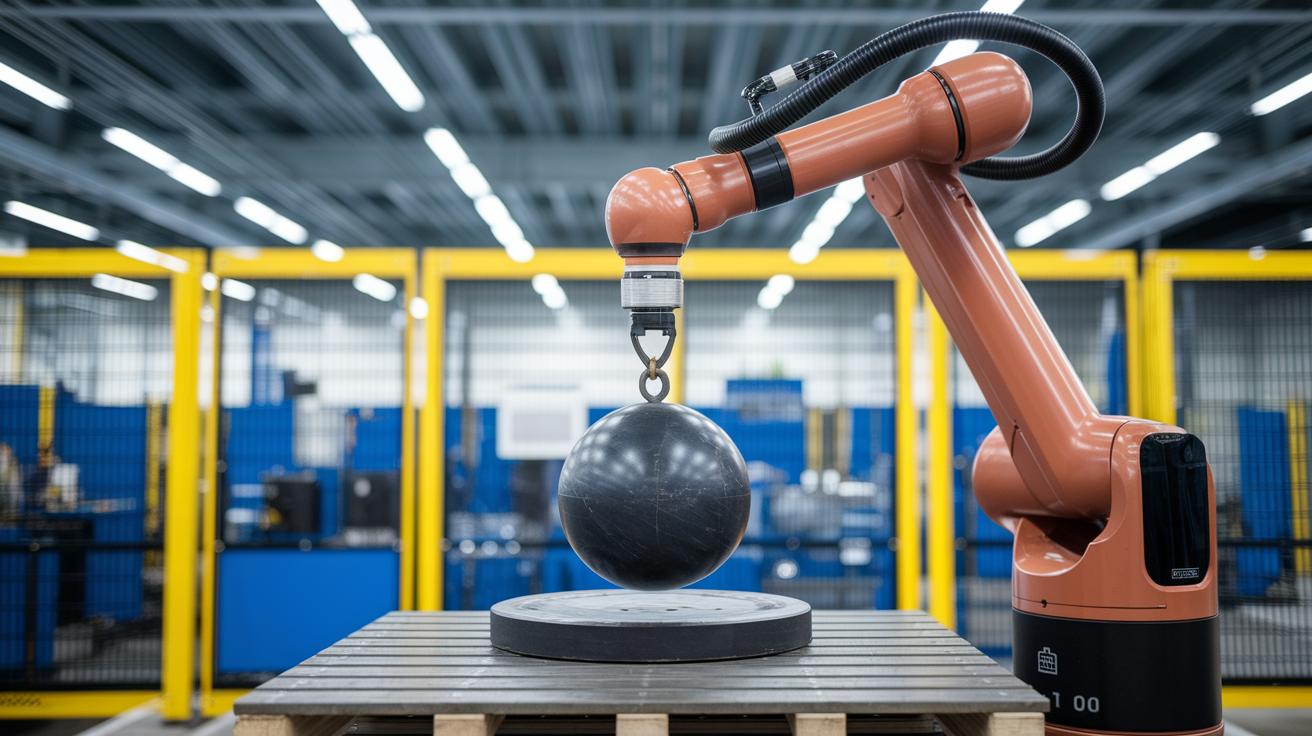
Let’s start with the fundamentals. The payload is essentially the maximum mass that the robot’s wrist can support. This includes everything from the gripper to its bracket and any extra end-effector you attach. One key idea here is that joint torque is simply force multiplied by distance. In other words, torque equals force times the length of the moment arm. So, if you know the force acting on a joint and the distance from that joint to the load, simply multiplying these gives you the torque on that joint.
Next, there’s another important formula that tells you how to calculate the moment from the payload. It goes like this: moment equals mass multiplied by gravitational acceleration and then multiplied by distance. Just plug in 9.81 m/s² for gravitational acceleration, and you get: moment = m × 9.81 × d. Even a small error in the mass or distance can lead to a big difference in the calculated moment, which can seriously affect the arm’s performance.
Manufacturers build in safety factors when they list payload capacities. This means that when you calculate the effective load capacity, you must consider every component attached to the wrist. Essentially, each joint’s moment should include contributions from both the payload and any extra tools on the arm's end.
Engineers use these formulas to make sure every force on the arm is taken into account. Accurate calculations not only boost performance but also keep everything safe and sound. In the end, parameters like mass, distance, and actuator force all work together to define the load capacity of a robotic arm, ensuring that it performs reliably during delicate tasks.
Key Factors Influencing Robotic Arm Load Capacity

Robotic arm load capacity comes down to a mix of design and mechanical strength. At its heart, how much weight an arm can lift depends on the strength of its joints, which is like how well the arm holds up under pressure, and the power of its actuators (motors that drive movement). Even a tiny change in arm length can shift the balance, affecting the force you need to lift a load. For instance, if you have a 2 kg end-effector working with a 3 kg workpiece, you end up with a 5 kg payload when you add a few extra bits.
The weight of the end-effector and its accessories matters a lot. The center of gravity, which is where most of the weight sits, also plays a big role in keeping things balanced. What the arm is made of, say, aluminum or titanium, can boost its strength and durability without making it too heavy. And if the arm speeds up really fast, those quick movements can add extra load because of dynamic forces.
- The strength of the joints and the power of the actuators decide how much load the joints can handle safely.
- The length of the arm and its center of gravity shape how leverage and balance work.
- The weight of the end-effector and any extra parts should be factored into your calculations.
Here's a tip: Try not to just add up the weights. Think about the extra force from the arm’s acceleration too, a small extra multiplier can really change the outcome.
Static vs Dynamic Robotic Arm Load Capacity Calculation
Static calculations only look at the pull of gravity on the payload plus any extra end-of-arm tools. It’s like putting your items on a kitchen scale – you only get the weight due to gravity. For instance, if a robotic arm is holding a 5 kg workpiece along with a 2 kg gripper, you simply add the masses while considering Earth's pull to get the static load capacity.
Dynamic calculations, however, take it a step further by including inertia. When the arm speeds up or slows down, extra forces come into play, making the effective load higher. This is because the way the mass is spread out and how fast the arm moves adds stress on the joints. In simple terms, if that same 7 kg load moves quickly, the arm experiences more strain, and sometimes it might need to slow down or even stop to prevent overloading.
- Static weight evaluation: Focuses solely on the gravitational pull of the workpiece and any attached tools.
- Dynamic mass simulation: Accounts for the extra load from acceleration, where inertia boosts the overall stress.
- Kinematics burden assessment: Considers speed, mass distribution, and the distance of the center-of-gravity to gauge the extra torque needed.
Even a small burst of acceleration can make a 7 kg load feel like 10 kg to a robotic arm.
Incorporating Safety Margins in Robotic Arm Load Capacity Calculation

When designing a robotic arm system, staying well within its rated limits is key to avoiding overload. Manufacturers intentionally include safety factors so that you typically only use about half of the arm's rated capacity. For example, if an arm is designed to handle 10 kg, running it at 5 kg or less gives you a healthy buffer against sudden disturbances or simple wear and tear. This careful approach really shines when the arm experiences unexpected jolts or when additional tools add extra load.
Here's how it works in practice:
- Safety margin evaluation compares what the manufacturer rated against the real-world conditions you expect.
- Engineers carefully check every load element – from the main object being moved to any tool attached – to ensure safety.
- Calculating the strength threshold helps decide how much extra capacity is available for any unexpected spike in load.
Try this approach: instead of powering a robot to its max, design it to run at about half its rated value. So if the rating is 10 kg, plan for a maximum of 5 kg. This not only protects the arm from excessive strain but also boosts its lifespan and reliability during everyday tasks.
Utilizing Payload Calculation Tools and Simulation for Robotic Arm Load Capacity
Modern design has come a long way with virtual testing. Today, you can quickly estimate a robotic arm's capacity using online payload calculators. These tools let you input details such as the weight of the end-effector, any attached tools, and even the workpiece. They even factor in things like mass, inertia, and how far the center of gravity is from the pivot. In plain language, you’re getting a fast preview of how much load the arm can safely handle, all while keeping safety and performance in check.
Online Payload Calculators
These web-based tools are like your quick tech sidekicks. They let you see how the arm’s estimated payload shifts in real time as you change variables. Just enter the arm’s mass details, and you’ll notice how the payload value adapts with different loads. It’s interactive and makes those early design steps feel almost like a fun experiment.
FEA Simulation Tools
Ever heard of FEA? It stands for Finite Element Analysis, a method that breaks down how structures behave under stress. In simple words, FEA simulation tools help engineers spot where the robotic arm might face high stress or strain when loaded. Imagine a software that lights up areas of potential weakness, so you can adjust the design to distribute the load more evenly. This not only backs up the estimates from the online calculator but also offers a closer look at potential design tweaks for better performance and safety.
Real-World Robotic Arm Load Capacity Case Studies
Imagine a robotic arm like the FANUC LR Mate 200iD, which usually handles about 4 to 7 kg. This falls right in the common range of 5 to 50 kg we see with these kinds of machines. When engineers work out the force needed for the arm’s reach, they check every element, from the workpiece to any tool attached, to be sure everything stays within safe limits.
Armed with precision, models such as the KUKA KR Agilus manage speed, accuracy, and load by carefully analyzing weight limits. At one facility, a robotic arm kept its balance perfectly even when the tool’s weight shifted. And here’s a cool fact: a small extra tool weighing just 1 kg can change the center-of-gravity and force a full recalibration of the setup.
SCARA robots are another popular choice in environments where speed and precision matter a lot. They typically move between 3 and 50 kg. Engineers fine-tune their capacity by accounting for every attached component, ensuring the actual load never goes beyond what’s safely allowed by the manufacturer.
Gantry robots introduce a whole new scale. Take the KUKA KR 1000 Titan, it lifts loads ranging from 750 to 1,300 kg. With these heavy-duty systems, a close review of load distribution and structural soundness is critical; one small error might affect the entire operation.
• Actuated reach force estimation helps predict the effort needed at each joint.
• Structural integrity reviews ensure smooth, long-term performance.
• Load-bearing limit analysis keeps the system safe, even with changing conditions.
Final Words
In the action, we explored core formulas for robotic arm load capacity calculation, stepped through torque and moment values, and weighed in on static versus dynamic analysis. We also checked out practical safety margins and simulation tools that turn dense figures into clear insights. Our review of real-world case studies wrapped up how these techniques help predict and balance loads effectively. It’s amazing to see how understanding the math behind the mechanics can boost confidence and spark more digital innovations. Keep pushing forward and stay inspired by what technology brings us next.
FAQ
Frequently Asked Questions
Robotic arm load capacity calculation excel
The robotic arm load capacity calculation excel uses key formulas to compute joint torque and moment arms, factoring in gravitational pull for a precise evaluation of load limits.
Robotic arm load capacity calculation example
The robotic arm load capacity calculation example shows how to apply formulas, including force times distance and summing moments, to assess each joint’s supported load accurately.
FANUC payload calculator
The FANUC payload calculator estimates the mass a robotic arm can manage by integrating design equations with manufacturer data, ensuring safe operational load predictions.
Robot arm design calculations PDF
The robot arm design calculations PDF offers a clear guide on computing joint torques, moment arms, and safety margins, helping validate the structural integrity of the robotic system.
Robotic arm design calculations
The robotic arm design calculations involve evaluating joint stresses and load distributions using mathematical formulas, ensuring each component meets safety criteria during operation.
Fanuc Payload Checker excel download
The Fanuc Payload Checker excel download is a practical tool that computes payload limits by comparing manufacturer specifications with calculated load values, streamlining design validation.
FRC arm calculator
The FRC arm calculator applies mathematical equations to estimate torque and load distribution, enabling quick determination of a robotic arm’s load capacity in competitive settings.
Torque required for robotic arm
The torque required for a robotic arm is determined by multiplying the force by the distance from the pivot point, ensuring each joint produces sufficient rotational force for movement.
What is the payload capacity of a robotic arm?
The payload capacity of a robotic arm details the maximum mass its wrist can support, including accessories, calculated with gravitational force and moment arm equations.
What is the load carrying capacity of a robot?
The load carrying capacity of a robot defines the total weight it can safely transport, incorporating both the tool and any additional components as specified by design limits.
How to calculate torque for a robotic arm?
The process to calculate torque for a robotic arm involves multiplying force by the distance from the rotation point, ensuring each joint’s capacity is accurately estimated.
What is the load capacity of the KUKA robot?
The load capacity of a KUKA robot depends on the specific model and design, with values set by the manufacturer after evaluating joint strength, geometry, and safety margins.