
Ever wonder why some robots glide so smoothly? It’s all thanks to a neat system called PID robotics (a control method that helps keep errors low by adjusting movements in real time). Think of it like a digital hand that fixes small mistakes before they pile up.
This system acts like a friendly referee, always making sure a robot’s path matches its intended direction. It quickly balances what the robot wants to do with what it's actually doing. In short, dynamic precision control gives robots that clever, accurate pulse that keeps every movement smart and on point.
PID Control Foundations for Robotics
PID control works like a smart helper for robots, always checking the difference between what you want to happen and what’s really going on. The Proportional part jumps into action right away. Say a mobile robot is moving at a speed of 8 when you need it to be 10, a proportional gain might take that error of 2 and quickly adjust the speed.
Then there’s the Integral component, which keeps a running total of past errors. Imagine a mechanical arm that gradually drifts off its planned course. Over time, even a small error builds up, and the integral action steps in to correct that cumulative shift, gently nudging the arm back on track.
The Derivative term is like having a lookout on duty. It measures how fast the error is changing, warning you about upcoming bumps in the road. This way, the control system can start smoothing things out before small issues turn into big ones.
Together, these three parts form a closed-loop feedback system that constantly monitors and adjusts itself. In robotics, this design is key for keeping a mobile robot balanced, regulating its speed, and stabilizing delicate mechanical movements.
Advanced PID Tuning Methods in Robotics

Tuning a PID controller is a lot like fine-tuning a digital instrument, you adjust the proportional, integral, and derivative parts until they all play together in perfect harmony. Many engineers favor the Ziegler-Nichols method. You begin with rough estimates and then adjust each gain until it feels just right. For example, setting KP to 2 means an error of 8 gives you an output of 16. But if your gain is too high, the system might start to oscillate, much like a mobile robot wobbling when its speed is over-corrected. It really highlights the need for careful calibration.
Simulation environments are a huge help here. Engineers test various KP, KI, and KD values in a virtual setting before taking them to a real robot. Imagine trying settings like KP=2, KI=0.5, and KD=1 in your simulation, watching your robot steady its movement, and then tweaking things when you notice any overshoot. This trial-and-error approach is crucial to prevent issues such as integral windup, where the integral term gathers too much error over time and pushes the system past its target.
Calibration is another big piece of the puzzle, kind of like adjusting the controls on a new car until you find the sweet spot for smooth driving. Engineers break down calibration into clear steps:
| Step | Description |
|---|---|
| Constant Load | Test under stable conditions to catch steady errors. |
| Gradual Gain Increase | Slowly ramp up the gains to observe the transient response. |
| Minor Disturbances | Introduce small disruptions to see how well the system recovers. |
Each step is designed to fine-tune the controller under different conditions.
The derivative component, which predicts future errors by examining the rate of change, must be managed with extra care. If filtering isn’t applied or if the loop rate is too slow, sensor noise can get amplified. Balancing these parameters pulls from both automated simulations and hands-on experiments. This ongoing tweaking ensures that every move your robot makes remains precise, regardless of changing conditions.
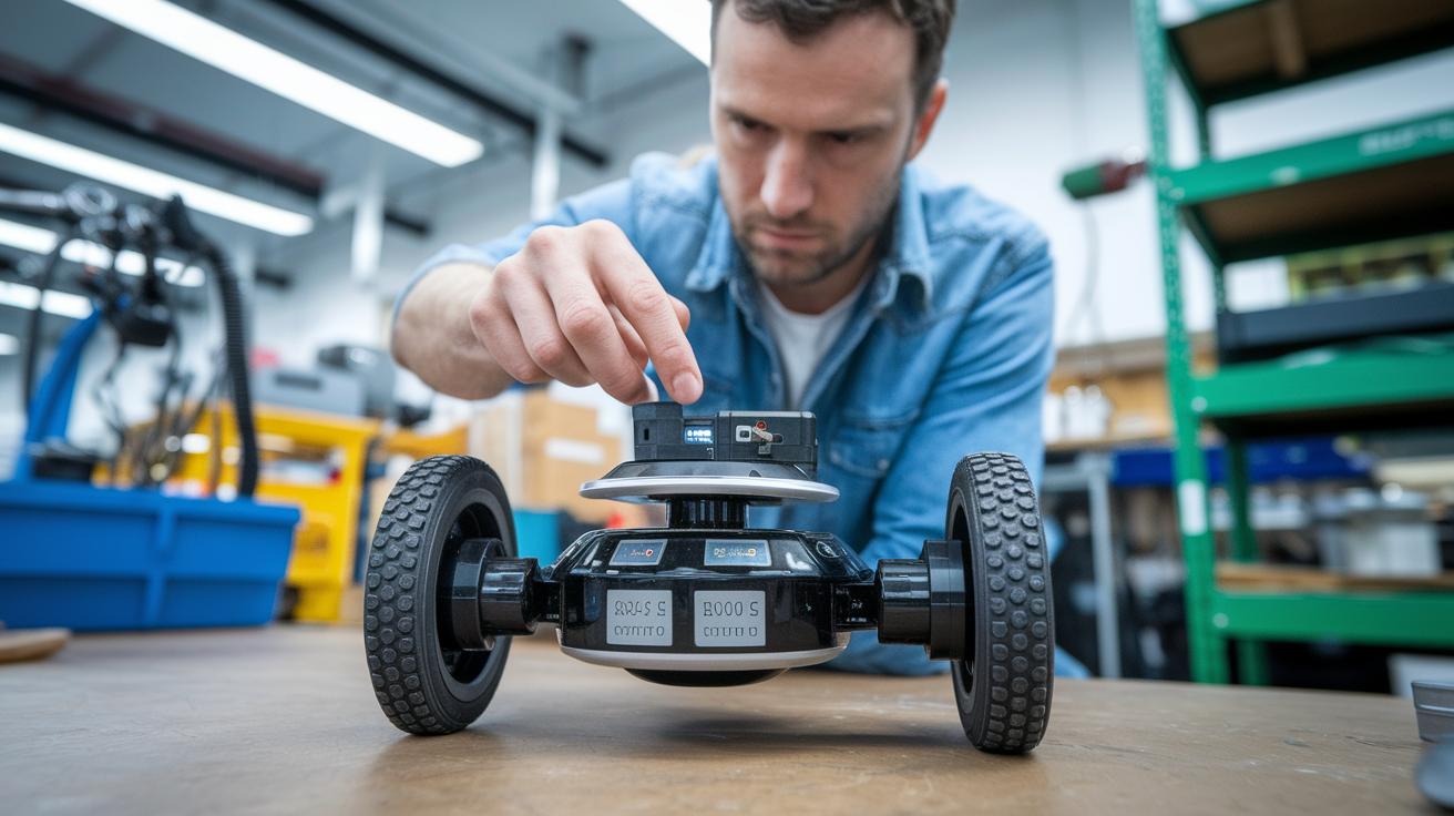
2. pid robotics: Dynamic Precision Control
Microcontroller platforms like Arduino and STM32 act as the digital brains behind PID loops, they sample sensor data at set intervals and adjust motor outputs as needed. Imagine a self-balancing robot that senses a slight lean and nudges its motors quickly. It’s like watching a tiny dance of balance in real time!
These controllers have their own limits, too. CPU speed and available memory decide how often the loop can run and what kinds of filters you can use. Picture writing code that grabs new data every 10 milliseconds from encoders and IMUs (devices that sense motion and orientation). Ever wonder how these tiny processors manage it all?
Line-tracking robots are another cool example. They use optical sensors to follow a designated path. The proportional part of the PID system kicks in when the robot strays from its line, while the derivative component smooths out sudden turns. In essence, reading sensor data at a high frequency with something like an Arduino allows for those super smooth, micro-adjustments on the fly.
Integrating sensors like encoders and IMUs with smart hardware design minimizes delays and boosts accuracy. From self-balancing setups to precise line-tracking, these digital PID loops teamed up with microcontrollers create robots that move reliably and with real precision. Fine-tuning parameters and optimizing loop rates help these systems adjust quickly to changing conditions.
PID Simulation Tools and Algorithm Design

Using simulation software is like fine-tuning a favorite instrument. MATLAB Control System Toolbox and Python’s SciPy library (a set of free tools for math and science) help you build a virtual model of your control system. You can simulate different responses – think of it as watching how a step, impulse, or quick change tests your system. For example, run a quick simulation to see how your control gains (the numbers that adjust your controller’s behavior) shape the curve of overshoot and settling time. This method lets you perfect your settings before any real-life testing.
Simulink block diagrams offer a neat, visual way to design PID loops. It’s like arranging colorful building blocks to see the effect of changing values. Engineers can easily try out different gain numbers to see how they affect steady errors and quick responses. And with online tuning tools, you can adjust KP, KI, and KD live while a graph updates right then and there – pretty cool, right?
Model-based design even lets you auto-generate embedded code straight from your simulation models. With these handy system modeling toolkits, you can quickly spot issues like overshoot or wobbly oscillations. Once you fine-tune your controller in this digital playground, it’s ready to handle the challenges of the real world.
Real-World PID Robotics Applications and Case Studies
PID control is becoming a real game changer in many robot systems, giving them a smart boost in performance. In one industrial setting, Stewart Platforms use multi-axis PID loops (which adjust commands based on error measurements) to drive very precise movements. One study even found that fine-tuning the controller settings made the simulator reach stability 40% faster, a clear sign of improved responsiveness.
Robotic arms, especially 4-Axis models, get a big lift from joint-level PID loops that keep their movements perfectly on track. Picture a robot arm assembling parts on a production line; with careful PID calibration, vibrations are kept low and the arm sticks to its intended path even when the load changes. A well-tuned system can take what might be a shaky operation and make it smooth and steady.
Mobile autonomous robots also show off the benefits of PID control. These robots often lean on a predominantly proportional strategy (where the response is quickly adjusted based on the current error) for tasks like dodging obstacles and following paths in warehouses. Imagine an automated delivery robot making quick, split-second moves to avoid obstacles, these immediate adjustments are crucial when every moment counts.
Differential drive systems, which are common in mobile platforms, rely on PID controllers to keep movement straight and turns well-coordinated. When each motor's gain is adjusted just right, the robot can handle curves with surprising smoothness and reliability. Think of it like a car tuned perfectly for a smooth drive on winding roads, where each tweak enhances overall stability.
Below are some practical improvements seen in documented cases:
- Better balance and sharper motion in various environments.
- Less overshooting, which leads to smoother operations.
- Increased stability during quick corrections and maneuvers.
Engineers are always digging into performance data to refine gains even further. Adjusting parameters in real-world conditions not only ramps up efficiency but also keeps performance steady despite changing loads. All these examples show that a finely tuned PID controller can really boost a robot’s overall capability and reliability.
Troubleshooting PID Control Challenges in Robotics
If your KP value is set too high, your robot might start wobbling like an unsteady table. For example, setting the controller to KP=4 could cause it to overshoot again and again. Try decreasing the derivative time constant, which helps control how fast your system reacts, or add a notch filter, a tool that cuts out specific troublesome frequencies, to smooth things out.
Sensor noise might also throw off your controller’s accuracy. Using a low-pass filter, which allows only the lower frequencies to pass, along with a smart sampling rate, can significantly reduce these unwanted fluctuations. Imagine a self-balancing robot receiving jittery signals from its IMU (a sensor that tracks motion); the low-pass filter smooths out those quick blips so the controller doesn’t react to every tiny bump.
Running diagnostic routines is super helpful for spotting issues. A step-response test, for instance, can show resonance peaks that may lead to instability. Think of it like playing a musical instrument, strike a note and listen to see if it rings out clear or if there’s any discord. You can also turn to frequency-domain analysis (a method that looks at how different frequencies affect the system) to better understand how your robot behaves.
System identification techniques are also essential. These methods capture the system’s dynamics, which means you can design and tune your control model more precisely. Engineers often simulate control scenarios using these techniques before testing them in a real environment.
- Step-response tests help catch oscillation tendencies.
- Frequency-domain analysis uncovers noise issues.
- System identification refines tuning by mapping out system behavior.
Regular diagnostics and smart tuning are key for keeping your robotics control both reliable and resistant to noise.
Final Words
In the action, we explored the nuts and bolts of PID control in robotics. We broke down key elements like why the proportional, integral, and derivative components matter in closing the feedback loop.
We also examined tuning methods, implementation on various platforms, simulation tools, real-world applications, and how to troubleshoot common issues. This article aims to boost your comfort with tech breakthroughs and help you integrate pid robotics into your projects. Time to power up and keep pushing digital boundaries.
FAQ
Q: What is a PID controller and its full form?
A: The PID controller stands for Proportional-Integral-Derivative. It adjusts outputs based on the error between the desired setpoint and the current state, ensuring precise control in robotic systems.
Q: What are KP, KI, and KD in a PID controller?
A: The KP, KI, and KD values represent the gains for the proportional, integral, and derivative components. They control immediate response, accumulated error correction, and prediction of future error changes.
Q: What is PID in robotics, automation, and mechatronics?
A: In robotics, automation, and mechatronics, PID stands for Proportional-Integral-Derivative. It uses a feedback loop to minimize errors and maintain performance, offering balanced control in various systems.
Q: How is a PID controller applied in robotics?
A: The PID controller in robotics continuously adjusts motor outputs using sensor feedback. It helps maintain balance, control speed, and track paths, making robots more stable and responsive during operation.
Q: What is an example of a PID controller in robotics?
A: A common example is a self-balancing robot that uses tilt-angle sensors and PID control to adjust motor speeds, keeping the robot upright even on uneven surfaces.
Q: What defines a PID robot line follower?
A: A PID robot line follower uses sensor inputs to determine its path. The PID algorithm adjusts the steering continuously, ensuring smooth and accurate line tracking without deviation.
Q: What does a PID controller diagram depict?
A: A PID controller diagram illustrates the feedback loop, showing how the proportional, integral, and derivative components interact. This visual helps explain how errors are minimized and control is maintained in robotic applications.
Q: What does PID robotics VEX refer to?
A: PID robotics VEX refers to the use of PID algorithms in VEX robotics platforms. It applies continuous error correction to enhance movement precision, balance, and overall performance in VEX robots.