
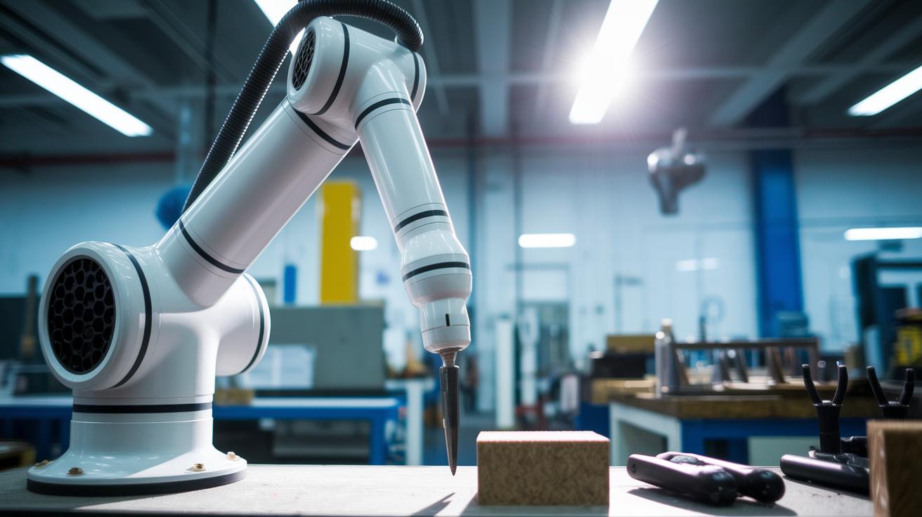
Have you ever seen a robotic arm in action? Imagine its parts gliding together like a cool dance, with every joint moving in perfect harmony.
When we say "robotic arm kinematics" (that is, the study of how each part moves), we mean breaking down how its joints and links work together to create smooth motion. Today, we’re cutting out the heavy technical talk and showing you how smart design makes these machines run smoothly.
Ever wonder what makes them tick? It's all about clever engineering that turns complex movement into a simple, reliable performance.
Fundamentals of Robotic Arm Kinematics: A Clear, Detailed Explanation

Imagine a robotic arm working like a well-choreographed dance. Each part, from its solid links to its swiveling or sliding joints, plays a critical role. It’s like a series of digital gears clicking into place, each joint’s movement adds up to position the tool at the very right spot. Even before our modern computers, engineers built clever machines that mimicked the human arm using purely mechanical methods.
At its core, a robotic arm is built around a simple idea: a chain of joints and links working together. The arm’s reach is measured in degrees of freedom, which tells you how many different ways it can move. One key idea is forward kinematics, this means if you know every joint’s position, you can work out exactly where the tool at the end of the arm is located. Then there’s inverse kinematics, which is a bit like a puzzle. It figures out what joint positions you need to hit a specific target.
Whether it’s a robotic welder or a pick-and-place machine, the same controls and motors help drive accurate movement. It’s the kind of systematic mapping, changing joint inputs into coordinated, smooth actions, that makes these machines truly remarkable. In our tech-driven world, such reliability and adaptability are the backbone of many industrial processes, pushing the boundaries of innovation every day.
Key Components of a Robotic Arm Kinematic Chain
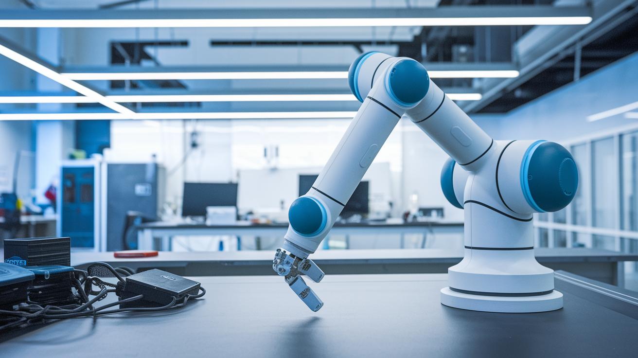
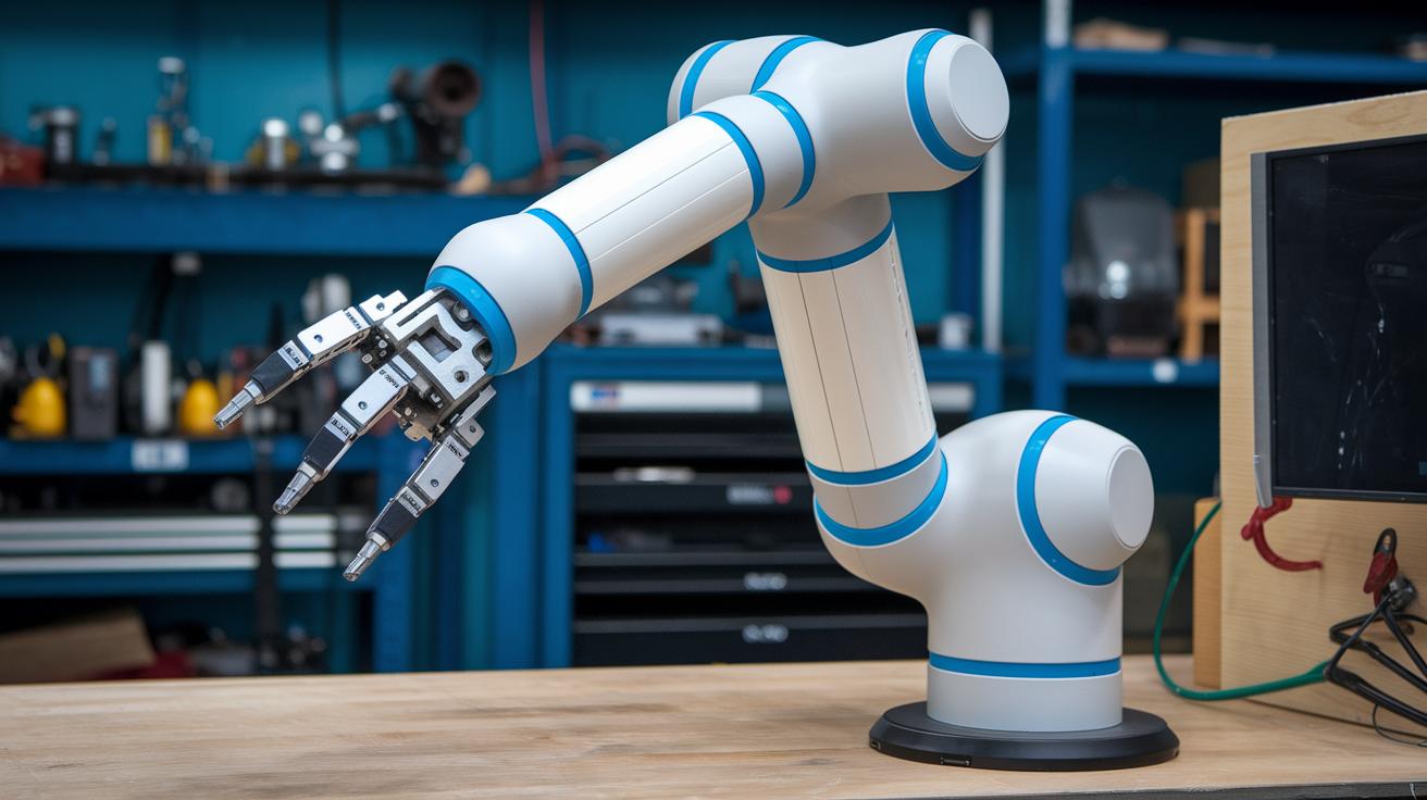
When you look at a robotic arm, every part has its own job to make sure it moves both smoothly and precisely. At the heart of it, solid links create the arm's structure and help keep it steady. Joints let the arm shift its position by either rotating or sliding, opening up plenty of movement options. Actuators, which are devices that turn energy (like electrical, hydraulic, or pneumatic power) into motion, push these joints with just the right force. And then there's the end effector, a gripper or specialized tool, that brings all this clever engineering into action by welding, picking up objects, or doing other tasks.
Each part matters because together they determine the arm's workspace and its ability to change directions. Their combined work makes sure the robotic arm performs reliably, even when the tasks get challenging.
- Links: strong segments that shape and support the arm
- Joints: movable connections that let the arm shift and rotate
- Actuators: devices that convert energy into the motion needed
- End Effector: the tool or gripper that carries out the job
In essence, all these elements form a connected chain that transforms simple joint moves into complex actions at the end effector. It’s a neat blend of hard engineering and careful design that makes every movement count.
Forward Kinematics for Robotic Arms: Predicting End Effector Motion
Forward kinematics takes the simple numbers from each joint and turns them into a clear view of where a robot’s hand lands in space. Think of each joint as a pivot that twists and shifts. We use a 4×4 homogeneous transformation matrix for each joint, a compact way to merge rotation and movement into one tool. When you multiply these matrices one after another from the robot’s base to its tip, you see how each twist and shift builds up to create the final position of the hand.
Start with a single joint’s rotation. Multiply that matrix by the next one, and the resulting product shows both the new angle and the shift that follows. Continue this pattern for every joint until you reach the end of the arm. In the end, you get a combined matrix that lays out the arm’s full motion. In simple terms, if you imagine a rotation as a twist and a translation as a shift, stacking these matrices clearly pinpoints where the tool makes contact.
This step-by-step process turns individual joint movements into one clear, digital blueprint for how the arm acts. Tools like the Kinematics and Dynamics Library (KDL), a set of ready-made functions for handling these calculations, make this process faster and more efficient in both factories and research labs. Ever wonder how a series of small moves adds up to something as precise as a robot’s hand? That’s the real magic of forward kinematics.
Inverse Kinematics of Robotic Arms: Computing Joint Parameters

Inverse kinematics flips the usual process. In forward kinematics, you know the joint angles and then calculate where the arm’s end lands. But with inverse kinematics, you start with a target point and work backwards to find the joint angles needed. This reverse method can get tricky, especially as the robot’s design becomes more detailed.
For simple robotic arms with only a few joints, you can use clear math formulas to get the answers. Think of it like solving an equation where you already know the result; once you pinpoint the target, the math gives you the exact angles. This approach is both fast and reliable when the arm’s structure is uncomplicated. Imagine setting up a two-link arm with a few bends, the computations are straightforward and swift.
On the other hand, when you’re dealing with complex robotic arms that have many joints, things get a bit more involved. In these cases, iterative numerical methods come into play. One common approach is the Jacobian pseudo-inverse method, which essentially tweaks the calculations repeatedly until it finds the right joint settings. This process might take a bit longer and sometimes needs careful adjustment to hit the mark. Tools like KDL and the ROS MoveIt! package use these methods to deliver real-time solutions for advanced robotic systems.
Denavit-Hartenberg Method: Transformation Matrices in Arm Kinematics
Ever marvel at how a robotic arm moves so precisely? The Denavit-Hartenberg method breaks things down into four key parameters that help us understand each joint's movement. First off, the joint angle (θi) tells us how much a joint rotates around the previous z-axis, like turning a knob to change direction. Then, the link offset (di) shows how far a part shifts along that same z-axis, setting the stage for the next movement.
Next up, the link length (ai) measures the straight-line distance along the current x-axis, kind of like setting the gap between two pieces. And the link twist (αi) is all about the subtle tilt around the current x-axis, giving the next piece just the right orientation. Together, these parameters let us break down complex motions into simpler rotations and shifts.
| Parameter | Symbol | Description |
|---|---|---|
| Joint Angle | θᵢ | Rotation about previous z-axis |
| Link Offset | dᵢ | Translation along previous z-axis |
| Link Length | aᵢ | Translation along current x-axis |
| Link Twist | αᵢ | Rotation about current x-axis |
By linking these transformation matrices one after another, we can map the entire arm's motion from the base right up to the end effector. Each matrix builds on the last one, ensuring that every turn and shift works in perfect harmony. Cool, right?
Jacobian Matrix and Singularity Analysis in Robotic Arm Velocity Mapping
The Jacobian matrix plays a vital role in robotic arm kinematics. It converts each joint’s speed into the overall linear and angular movement of the arm’s end, kind of like turning a bunch of dial tweaks into one fluid motion. Imagine carefully turning several knobs at once, each contributing to a smooth, coordinated move.
Singularities really throw a wrench in the works. They happen when the determinant of the matrix hits zero, and suddenly the mapping stops working properly. In this state, even the tiniest movement might demand insanely high, sometimes even infinite, joint speeds. Think of it like two gears meshing so perfectly that turning one barely nudges the other, pretty impractical, right?
A similar idea shows up in differential drive systems. Here, the speeds of the left and right wheels, labeled ωL and ωR, work with measures like the base width and wheel radius to make the whole system move. This example underlines just how essential accurate velocity mapping is for smooth and controlled motion.
Engineers tackle these tricky spots with smart strategies. They design robot movement paths to dodge problematic zones and use adaptive control algorithms to ease through near-singular postures. These methods help ensure that the arm’s motions remain predictable and safe, even when navigating challenging configurations.
Kinematic Simulation Tools and Solver Libraries for Robotic Arms

Solver libraries like Orocos KDL, ROS MoveIt!, and the MATLAB Robotics Toolbox help bring ideas into reality. They have ready-made functions that manage forward and inverse kinematics (that’s the math behind moving robotic joints exactly how you want), letting you spend more time perfecting your robot’s dance rather than creating new algorithms.
Take ROS MoveIt!, for example. It plans out paths and works with simulation tools like Gazebo and RViz. These simulators light up your screen with live feedback, so you can see exactly how each joint move changes your robot’s path, kind of like watching a digital puppet show in real time.
Many experts love that ROS plugin frameworks let you switch kinematic backends on the fly. This versatility is super handy when you’re testing how different solvers perform in various settings. Whether your project needs a powerhouse solution for an industrial arm or a nimble option for a sleek research build, mixing these libraries with simulation environments makes testing system dynamics, trajectory precision, and obstacle dodging a breeze. Plus, with the smooth integration of sensor feedback and real-time control loops, these tools have become essential for today’s robotics innovations.
When you're picking out the right library for your robot, think about how well it meshes with your hardware and software, how easily it plugs into your simulation setup, and what kind of community backing you have for updates and troubleshooting. These factors ensure your robot moves with confidence and consistency every time.
Real-Time Control Integration: ROS and Motion Management in Robotic Arms
Real-time control systems such as ROS Control and Orocos RTT mix kinematic solvers, sensor data, and actuator actions. For instance, sensor readings from devices like encoders go into a PID loop (a control method that adjusts outputs when there is a difference between desired and actual movements) and help fine-tune the signals going to the actuators. This method keeps the arm moving smoothly, even when things change quickly.
Software and hardware need to work side-by-side. By linking the Kinematics and Dynamics Library (KDL) inside ROS packages with up-to-date sensor information and motor drivers, the system adapts fast to environmental shifts. It’s like having a smart conversation between code and the physical parts of the arm, ensuring all movements are in perfect step.
Calibrating sensors and adjusting PID loops are essential for accurate moves. Regular sensor calibration makes sure data stays in check, while careful PID tuning minimizes delays and prevents overshoots. In short, syncing solver updates with hardware drivers means every command matches the arm’s physical movements, giving you performance you can count on.
Final Words
In the action, we explored how robotic arms move through smart joint calculations and clear kinematic chains. We broke down complex topics like forward and inverse methods, matrix building, and velocity mappings into bite-sized, practical insights.
The discussion also covered simulation tools and real-time control strategies, showing how simple math meets innovative digital solutions. Robotic arm kinematics explained represents a fresh look at integrating tech into everyday challenges. The future feels bright and full of promise!
FAQ
Q: What is robot kinematics and the kinematics of a robotic arm?
A: Robot kinematics defines how a robotic arm moves by describing the arrangement of joints and links. It calculates end-effector positions and orientations from given joint values.
Q: How does a robotic arm move?
A: A robotic arm moves by coordinating its joints through actuators. This coordinated motion creates a kinematic chain that maps joint movements into precise end-effector trajectories.
Q: What are forward and inverse kinematics in robotic arms?
A: Forward kinematics computes the end-effector’s position from known joint angles, while inverse kinematics determines the required joint parameters to reach a specific target position.
Q: What is the inverse kinematics problem for a robotic arm?
A: The inverse kinematics problem involves calculating the necessary joint angles that will move the arm’s end effector to a desired position and orientation in space.
Q: Where can I find resources, PDFs, or courses on robot kinematics and dynamics?
A: Educational materials like PDFs and beginner courses simplify robot kinematics and dynamics. They offer clear explanations of joint movements, kinematic chains, and dynamic behaviors for easy comprehension.